A common problem for any fully enclosed NEMA 4/4X, IP65/66 rated display is exactly how to get the cables in and out of the enclosure while maintaining a water-tight seal. This problem has been approached in a variety of ways by equipment suppliers, but usually the solution involves either conduit, some sort of compression gland, or watertight external connectors with custom mated cables.
Update Sept. 2018 – in the years since this article was written, our cable exit plate offering has expanded to include a combination conduit/compression plate. For full details, visit our cable exit option page.
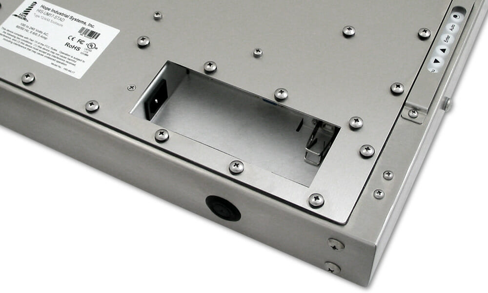
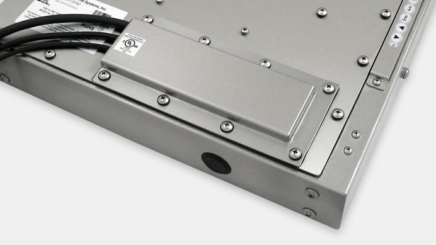
At Hope Industrial, we have found that the best solution is to provide a variety of solutions, and to let our customer choose which works best for their application. To support the approach, we have designed a standard cable exit cavity that is the same on all of our Universal Mount fully-enclosed displays, along with a wide selection of “cover plates” that are interchangeable. Today’s post will discuss the newest of these options: the NEMA 4/4X (IP65/66) Compression Gland Cable Exit.
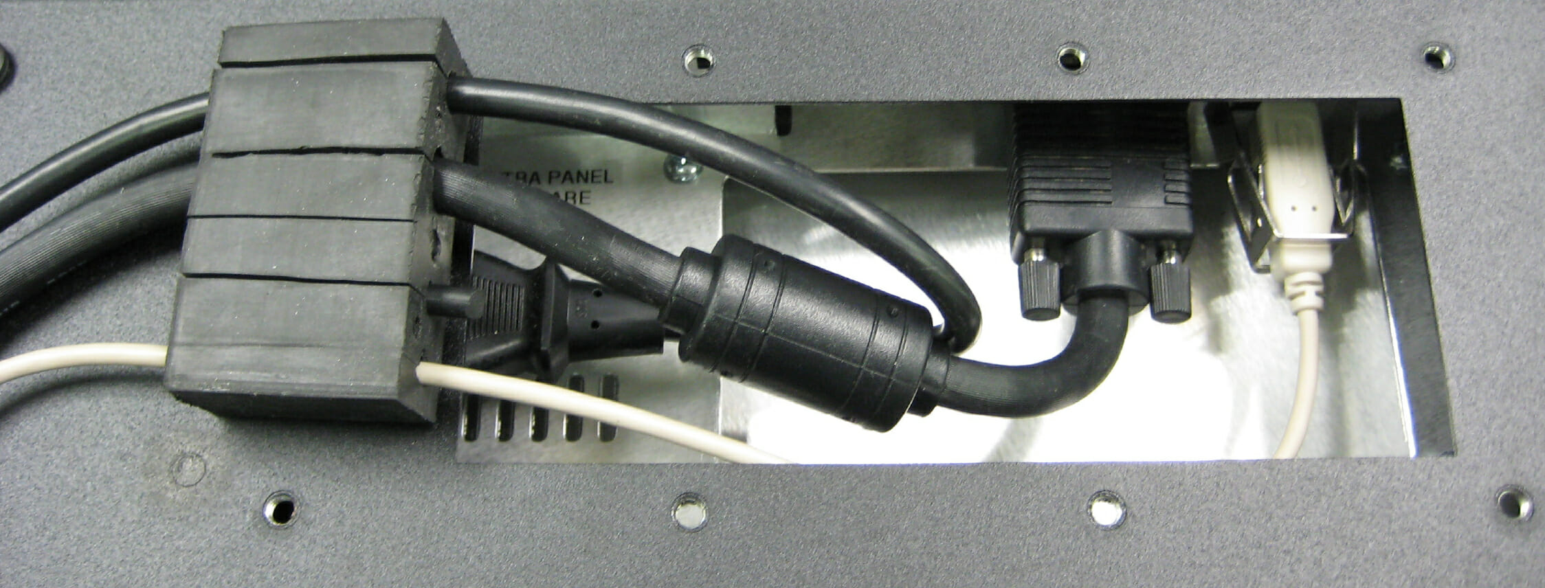
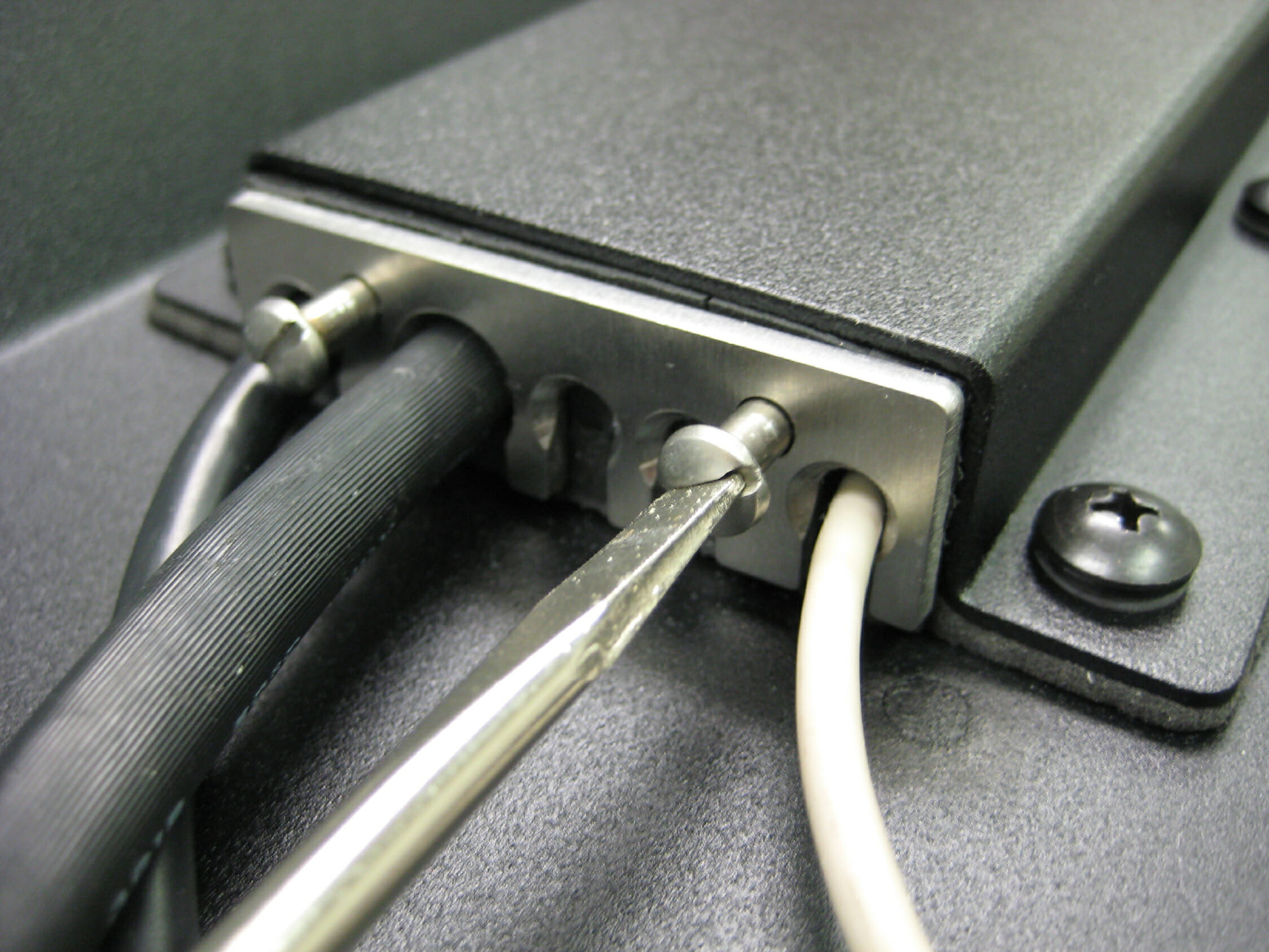
The principle behind this option is nothing new: cables are passed through a rubber gland which is inserted into a sealing cavity, with a means of compressing the gland to seal the cables to the cavity. This approach has a lot of benefits:
- It is easy to install in the field
- Cables can be easily removed, replaced, or repositioned
- No special cables are needed; anything in the specified diameter range will work
- A full, water-tight, wash down seal is easily achieved
Our design incorporates all of these benefits into a cover plate that fits the standard rear opening of any of our Universal Mount Industrial Touch Screens. To install onto a display, the user must simply remove the rubber gland from its housing, remove the rubber stoppers from the pre-cut cable exit holes, push cables through the slits, then install the cover plate and tighten the compression screws. For a better idea of how this works, see the images below.